Overview of HK amplifier
Please note that this is just my understanding of the amplifier from my inspection and investigation, there may be some errors.
Block Diagram

Amplifier PCB images
PCB Top view and component functions (Hover and click for more information)⇐ Class D amplifier, output filter magnetics ⇒Filters the switching outputs of the Class D amplifers
⇑
⇐ Power Supply Components⇒
⇓Switching and boost regulators for all of the components.
⇐ Power Supply Components⇒
⇓Switching and boost regulators for all of the components.

PCB bottom view and component functions (Hover and click for more information)
⇐ DDRDDR memory for the DSP's TDA7803A

MOST bus
The Polestar MOST bus is an optical bus that runs at 150MHZ (MOST150)Please note that aftermarket audio equipment like the Valse MOST150, Audison BIT-DMI do not work in the Polestar.
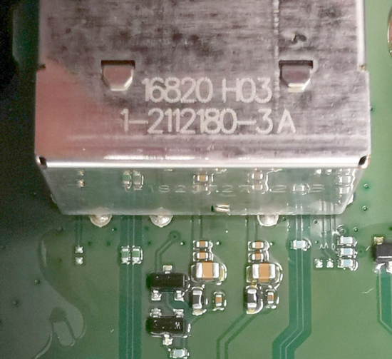
MOST optical to electrical connector (TE Connectivity, 1-2112180-3)
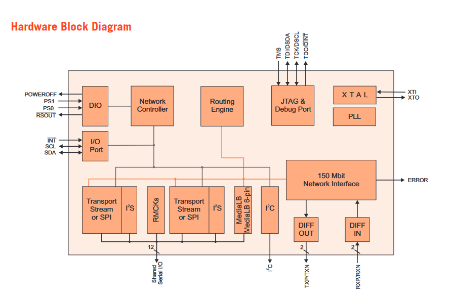
Microchip MOST Controller, SMSC OS81110AF
This is the key component interfacing the amplifier to the MOST bus. It outputs 2x I2s audio channels and links the MOST bus to the amplifier CPU (FPGA)
The main output of this IC is the MediaLB into the FPGA. There are two I2S outputs but they are only 8bit and 16bit mono.
I've not yet attached a DAC to them to investigate any further.


Audio Amplifier Power stages
There are 3 IC's that take the I2S digital data and convert it to audio.1x TDA7803A (ST Microelectronics)
2x FDA801 (ST Microelectronics)
TDA7803A
Class SB-I, Audio Power Amplifier.
4x28W @ 4R (10%THD)
I2S input, 4x power outputs
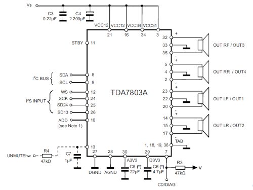
This is heatsinked to the outer case of the amplifier to keep it cool
Class SB-I amplifiers are less efficient than Class D but higher quality.
This device powers the front tweeters and rear surround speakers
SB-I = Single-ended Bridge - improved (Similar to Class A/B amplifiers, but higher efficiency.)
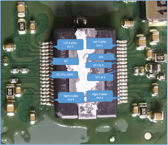
FDA801
Class D, Audio Power Amplifier.
4x27W @ 4R (10%THD)
I2S input (only one of the two I2S inputs is used. 4x outputs)

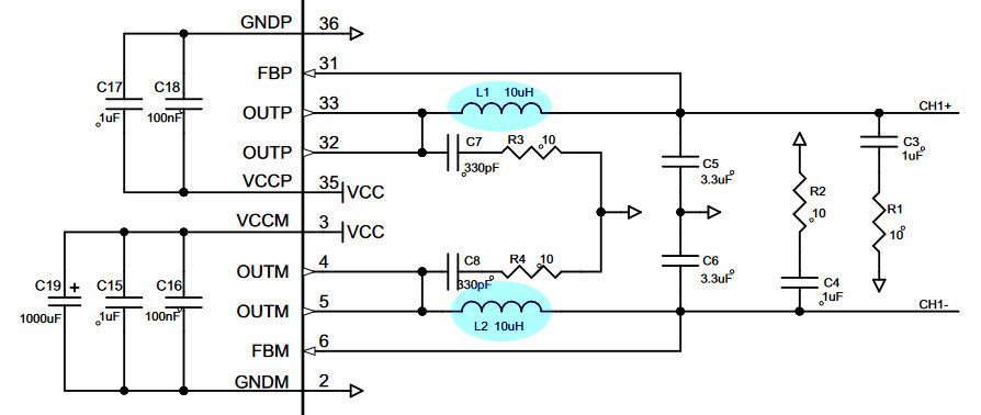
This is again heatsinked to the outer case of the amplifier to keep it cool
Class D amplifiers use high frequency switching to make them more efficient. The trade-off is a lower quality output.
This powers the subwoofers and door speakers.
This amplification method requires filtering before the signal is sent to the speakers.
I2S Audio
All three of the final power amplifier IC's (1x TDA7803A & 2x FDA801) are supplied in I2S audio format.
The two FDA801's are supplied from a single I2S (TDM) signal that carries 8x audio channels.
Each IC is configured to use the top or bottom 4 channels.
Below is a capture of the 16 bit TDM data:-

There are also two mono I2S signals that come out of the OS81110AF MOST150 Phy on SRX2 and SRX3.
SRX3 appears to be 8bit mono, SRX2 is 16 bit mono.
I have not put these signals though a DAC yet. More will follow on this.
16bit OS81110AF signal:-

CPU
The CPU function consists of two IC's a CPLD and an FPGACPU functions include:-
MOST bus communication, handshaking to say it's present on the bus, conveying serial number* and diagnostics
I2C configuration of the amplifier stages
MediaLB interface between the MOST150 phy and the DSP
DSP configuration?
Thermal monitoring
* Polestar reportedly add unique security ID's to their amplifiers. This means that parts cannot be moved from one vehicle to another
or upgraded without factory assistance.
ALTERA MAX V 5M240Z (CPLD5M240ZT100A5N) Support IC for the FPGA
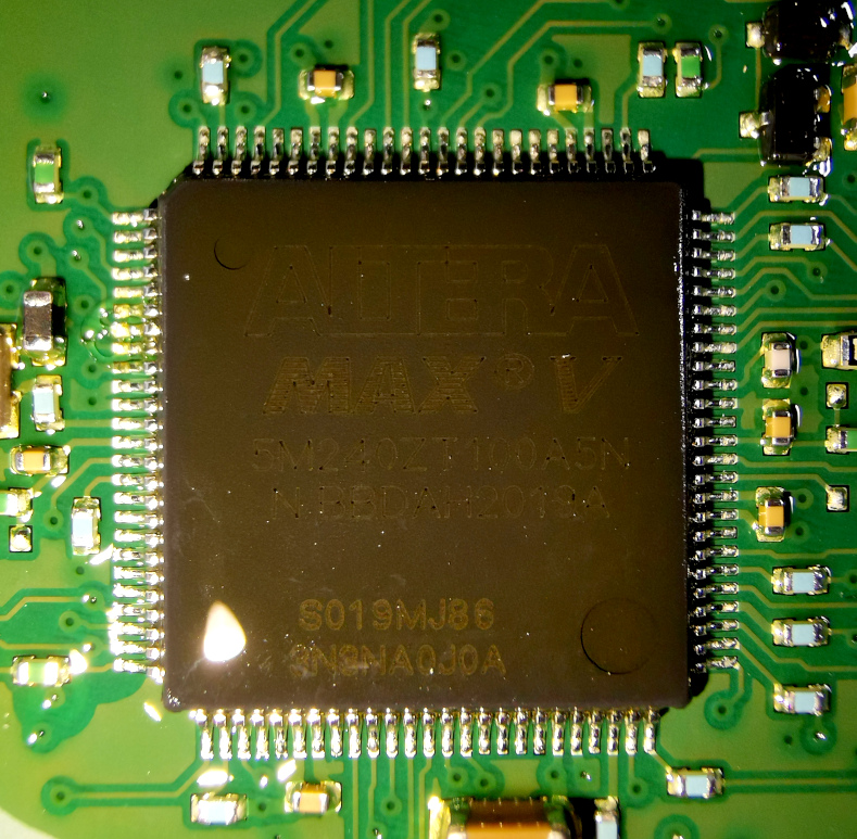

FPGA
I have very little information on the actual part number and manufacturer of this component.
Its connectivity and implementation confirms that it is an FPGA.
Markings 10303, TD47194, 4T, 2017
4T = Speed grade, 2017 = date code, week 17 2020

DSPs
There are two DSP (Digital Signal Processors) ICs within the amplifier.Both DSP's receive their signals via the FPGA.
ADW95096Z (ADSP-21469) this DSP interfaces directly to the audio power amplifier ICs.
This IC also has a DDR2 interface.
ADW95119Z (ADSP-21489) this works in conjunction with the ADW95096.

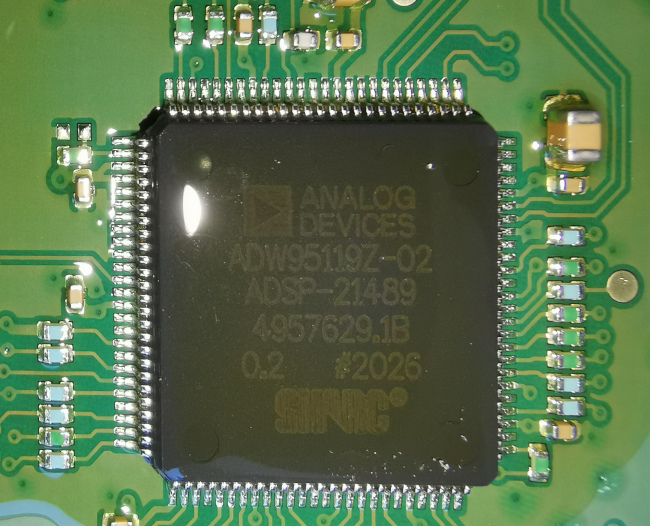
Quad temperature sensor connected to the ADW95119Z via SMBUS.
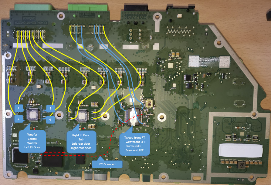
DSP -> Amplifier -> Speaker routing paths
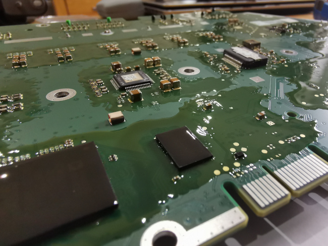
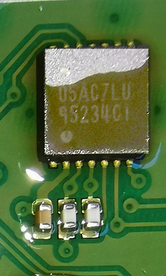
The electronic components on the PCB are protected by a moisture resistant covering, a conformal coating.
This also helps to a small degree protecting the components against shock and vibration.
